We start blender and click the splash screen away.
3.1. Mesh cube
The goal of this step is to create a mesh box in blender and make it desired size. Blender is ready, showing the empty scene. To add a cube we press the [Shift+A] key. This opens a menu where we select a cube to create it at the position of the 3D cursor:

Now we save the actual file somewhere under appropriate name, say ‘meshbox’. At this point we can also rename the cube and the mesh inside, than when we upload the mesh, SL will name it properly. We have a single object but for multiobject scenes, renaming is important. To rename the cube, right-click it in the outliner and hit ‘Rename’ menu button.
Info: The 3D cursor is a red-white circle in the middle of 3DView Editor. The cursor position is selected via left mouse button. Clicking somewhere occasionally will move the 3D cursor there so the later added cube will appear there. If this happen to you, and you not created the cube, you can use the [Shift+C] key to move the 3D cursor to the origin.
Alternatively you can also see and change the position of the 3D cursor on the properties panel. If you noticed the mistake after adding the cube, you can simply edit the cube position instead of deleting it and recreating at the origin:

When the cube is created it is selected usually (outlined orange.) If not, please click it with the right mouse button or use the [A] key (because only the cube is visible, the shortcut selects nothing else.)
Info: In blender, you select elements with the right mouse button; held [Shift] key extends the selection. Also the [A] key is extremely useful: If something is selected, the key deselects it, if nothing is selected, the key selects everything visible.
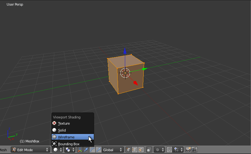
When the cube is selected, we press the [Tab] key, this switches blender into edit mode. Now the cube turns orange and we can edit each vertex separately. Instead of [Tab] button, we can also use the mode selection menu in the symbol bar of 3DView Editor. Near the mode selector, we find the shading selector and activate wireframe sading:

Info: The mouse wheel is used to zoom in and out the scene. Alternatively we can use the middle mouse button while held the [Strg] key, or with mouse emulation, the left mouse button with held [Strg+Alt] keys. We use one of the methods to look closer at the cube.
The last but perhaps not final step is scaling the cube to half. We remember, blender created the cube with the edge length of 2 meters. We need it to be 1m edge length, so we must scale it to 50%, e.g. 0.5 of the original size.
The easiest method to scale things is using the scale transformation: The cube is all selected (if not, just press [A] once or twice until it is all orange) so we press [S] and the mouse pointer turns into scale mode.
Now the symbol bar of the 3DView Editor displays coefficients the selected elements scaled in X, Y and Z directions. 1.0 means not scaled. We now have to move the mouse until each number displays 0.5. With left-clicking into 3DView the cube is finally scaled:


Tip: If while operation the [Strg] key is held, blender runs the current operation (i.e. scaling) in steps, which makes very easy to match desired scale value. Right-clicking into 3DView aborts the current operation.
Info: The most used mesh transformations are scaling (the key [S]), rotation (the key [R]) and translation (the key [G].) Scale transformation we used right now, others we may use later.
If we switch to Object mode (Press [Tab] key please), we can see, the cube is now 1m of edge length (if not, you have scaled not correctly, please revoke the scale operation and repeat it again.):

3.2. Attaching an UV Map
In this step we will attach an UV Map to the mesh cube making it texture-able inworld. The reason: When we upload the cube now, it will be unable to display the given image like the system box does. SL doesn’t know how yet how to do that, so we have to specify this information. The one way to do that is giving the cube an UVMap by unwrapping the mesh.
You can understand unwrapping if you imagine the cube wrapped by paper. We specify now on what edges we have to cut this paper in order we can make it flat. Before we do so, we remember the texture orientation on the system box faces: The negative Y side was ‘front’ and when looking at it we can rotate the cube left, right, up and down and the face textures remain vertically oriented.
This means we cut the cube edges starting from the front side (negative Y.) So, we switch back into edit mode and deselect the cube ([Tab] key, than once or twice the [A] key until it is dark.)
Now we activate edge selection (switcher is in symbol bar of 3DView Editor) and while holding the [Strg] key we right-click on every edge that needs a cut in the wrapping paper (last selected edge appears white, not orange.):

Now we have to tell blender these edges are seams of the wrapping paper. Either the menu Mesh/Edges/Mark Seam or the button Mark Seam in the left panel:


If we deselect all edges we can easilly see the seam-marked edges, they are shown red:

Now if we deselected them, we select all edges again and then we unwrap the mesh: The [U] key, than Unwrap button:

Changed something? Yes, now blender has created an UV Map for the cube and set seams. To see it, we must reveal the UVImage editor by moving the 3DView symbol bar up:

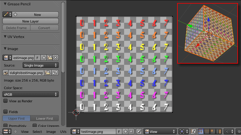
The UVMap view displays how the texture given the cube will wrap around it, what parts of the picture would be shown where and how. But we can now even assign a test image and see the result in the 3DView. As test image we will use this one::

When we select the image in blender, it appears in the UVImage editor:


But not on the mesh cube in the 3DView editor. To see the image also there, we have to select the texture shading:

While inspecting the cube we can see that some faces are dark. Reason: The light of the (in last tutorial hidden) lamp falls at that faces in a bad angle or not reaches them at all, leaving the faces black. There are two solutions for that problem: We can add another light source to shine at the dark faces.
A simpler but radical one is deleting the hidden lamp. If there is no light source in the scene, blender seems to use a default light which is not directed and lights all faces of the cube perfectly. I guess otherwise the scene would be black and we would not know where to put the first light.
However, deleting the lamp is easy: Right-click it in outliner and then hit ‘Delete’ button in menu. If the cube became deselected, please select it again and enter the edit mode:

Now we can look around the cube and inspect every face:

Info: There are two ways to rotate the 3D view around the scene, i.e. the cube in this case. The first way is using the middle mouse button, or with mouse emulation the left mouse button while holding [Alt] key.
Alternatively we can use the num pad buttons: The [n1], [n3] and [n7] keys switch to the front, right and top views respectively. The [Strg+n1], [Strg+n3] and [Strg+n7] keys switch to the back, left and bottom views respectively. The [n5] key switches between the perspective and orthogonal views. Finally, the [n4], [n2], [n6] and [n8] keys rotate the view around the scene.
However, we can see now that every face of the cube displays another segment of the assigned image. This is different to how the system box displays the images; the system box displays the full image if it is not scaled. To achieve the same effect with the mesh cube, we must maximize the UVMap of every face, making so the UVMaps of the faces overlap.
First we deselect the UVMap (press [A] key while the pointer is in the UVImage Editor, so the UVMap turns white, not orange.) Than we ensure the vertex selection in the UVImage editor is active.
Finally we switch two important settings on: ‘Snap to Pixels’ and ‘Constrain to Image Bounds’. Now if we move selected vertexes in the UV map, we can't move them out of image area (constrained) and the coordinates wil never become something ugly like 0.00000125:

Now we return to the 3DView editor, there we activate the face selection, deselect the cube and select a single face, e.g. front. The UVMap only shows now the single rectangle giving the image area mapped to the selected cube face. The goal now is to make this face to use the whole image.
To do so we select a vertex, e.g. left lower one (right click on it.) The vertex has the coordinate (64, 64). We can change the coordinate by hand to (0, 0) or simply press the [G] key (translation operation) and pull the vertex to the left lower image corner:


The same operation we repeat with each other vertex until the UVMap of the selected face is maximized. After it is done, we deselect the UVMap so no vertex is selected:

Important: After the face is done we should deselect the UVMap before working on the next face, otherwise the still selected vertexes move with visibly selected, causing us some work and frustrations later.
So, we deselect the UVMap of the current face of the cube, than deselect the cube and select it’s another face and repeat the work, than next face and so on, until all six faces are done. After this is done, we can select the whole cube and look at the UVMap, it should show only a single rectangle like this (in fact these are six rectangles at same place):
If your result is like in the picture, you are done with this step.
3.3. Separating the mesh faces
Now we make the mesh cube to have six independent faces, not just one: When we upload the cube to SL, we would realize, although we can give the cube an image now, the image will appear at each face of the cube, selecting a separate image for each face is not possible – because the cube has in fact a single face. Also scripts would see only this face with number 0.
The final step in our project is changing that. Before we can start with it, we have to open the materials tab: We minimize the properties panel and enlarge the outliner panel (both by moving the border), than we can see the symbol for the materials tab and click on it:

Now we should take a break and remember the order of the system cube faces. The order defines under what number the script access what face. The face order was:
Positive Z – negative Y – positive X – positive Y – negative X – negative Z.
This is the order we assign materials to the faces. Back to the project. The cube has six faces, so we need six materials. We now create six materials slot by hitting the plus symbol right to the empty slot list. The slots appear empty, we select the first of them and push the ‘New ‘ button below the list:


Blender creates a new material for the selected slot. We should rename each material so we can recognize it. The name is not important, important is the number of the material slot and what face it is assigned.
We select a name schema that describes the name of the face, the material is meant to, the face axis and axis direction, e.g.‘top (pos x)’. Than we can or even should give the material a distinct color, we use the axix color, i.e. blue for z axis, and the intensity: 0.5 for negative side, 1.0 for positive side:


Than we repeat the same for further materials: Select the empty slots, than add material, than rename and recolor the material. The LSL face numbers, slot numbers and material names are:
- Face 0 (slot 1) – top (pos z) – light blue
- Face 1 (slot 2) – front (neg y) – dark green
- Face 2 (slot 3) – right (pos x) – light red
- Face 3 (slot 4) – back (pos y) – light green
- Face 4 (slot 5) – left (neg x) – dark red
- Face 5 (slot 6) – bottom (neg z) – dark blue

After all materials are prepared, we can assign them to faces in the correct order. Here we benefit from the chosen material names. We ensure the 3DView editor is in face selection, and activate the wireframe shading. Now we select the top face and the material named ‘top’. Than hit the Assign button in the material editor:

Than we select another face, the material meant for the face and hit Assign button again, and so on until all materials are set. To test if we did everything good, we have two possibilities: If we select a face in the 3DView editor, blender selects the assigned material, so we can see if this is right one. Another way is to deselect the cube, select a material and the ‘Select’ button in the material editor, blender selects the face the material is assigned to:

The third way to test material assignment give us the colors we have given to materials. If we switch the 3DView to the solide shading, the faces turn into material colors, so we just can take a look to see if the faces have correct materials set:

After everything is checked to be ok, we are done with this step. We can export the cube as collada file so we can upload it to SL, the menu 'File/Export/Collada'.
3.4. Uploading and inworld test
Now we upload the mesh cube to SL and take the final look at it. Uploading mesh is bound on two requirements by LL: You must set your payment info on file and run a mesh tutorial, so LL knows you know what is right and what not by creating mesh content, and once you uploaded an illegal content LL knows how to reach you. But since our cube is neither grabbed from internet nor uses trademarks, it is definitely legal.
Tip: Before you upload mesh in main grid (Agni), test your build in the beta grid (Aditi.) This way you not lose money while correcting mistakes. Once you are satisfied, you can upload your model in main grid.
The cube has a very simple geometry. So it is not very wrong to upload it with maximum quality: Using the same model for all levels of detail. The MeshBox in GlasBox packages will be upload this way.
Last check. Here is how our mesh cube looks inworld when directly rezzed. The faces even keep the material colors, so we can check again if we set right materials.

And here if we use the script from the section 2. I think the goal is reached:

That’s all at the moment. Hope you liked so much text and pictures :)
Next part: GlassBox

Keine Kommentare:
Kommentar veröffentlichen